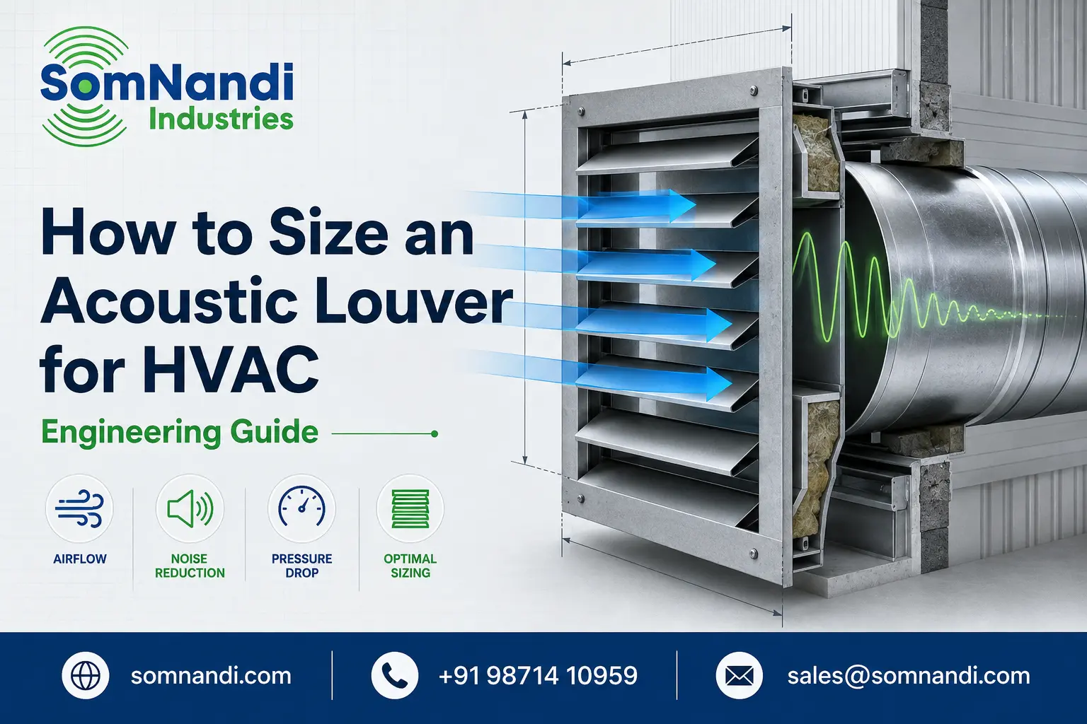
An acoustic louver for HVAC must perform two jobs simultaneously: allow enough air to pass through the opening and reduce noise escaping from the equipment. Selecting one solely by its outside dimensions can restrict airflow, increase fan energy consumption or provide inadequate sound reduction.
Correct sizing requires four main inputs: airflow, available free area, acceptable pressure drop and required insertion loss. Outdoor installations must also account for rain, corrosion and environmental exposure.
Quick Answer: To size an acoustic louver, convert the required airflow into cubic metres per second, divide it by the selected free-area velocity and then divide the resulting free area by the louver’s certified free-area ratio.
This calculation provides a preliminary face area. The final model must still be checked against manufacturer pressure-drop and acoustic-performance data.
Collect the HVAC Design Information
Before selecting a louver, obtain:
- Required intake or exhaust airflow in m³/h
- Maximum acceptable system pressure drop in pascals
- Available wall-opening dimensions
- Equipment noise levels across octave-frequency bands
- Required sound level at the nearest receiver
- Airflow direction and expected weather exposure
Airflow alone is insufficient. Two louvers with identical outside dimensions can have different free areas and pressure drops because their blade depth, spacing and internal geometry differ.
The AMCA louver application manual covers louver selection for pressure drop, water penetration and sound reduction. It also warns designers to consider system effects when applying laboratory performance data.
Calculate the Required Free Area
Consider an HVAC plant room requiring 10,000 m³/h of exhaust air.
First, convert the airflow:
10,000 ÷ 3,600 = 2.78 m³/s
Assume a preliminary design free-area velocity of 2.5 m/s. This value is only an example; the project engineer must choose the appropriate velocity for the application.
Required free area:
2.78 ÷ 2.5 = 1.11 m²
If the proposed acoustic louver has a certified free-area ratio of 45%, the required face area is:
1.11 ÷ 0.45 = 2.47 m²
A nominal opening of 1.6 m × 1.6 m provides 2.56 m² of face area and may therefore be a suitable starting point.
However, free-area percentage is not a complete measure of performance. Blade geometry can cause two products with similar free areas to produce different pressure losses.
Check Pressure Drop
Pressure drop is the resistance created as air passes between the acoustic blades. Higher resistance forces the fan to work harder and can reduce the actual airflow delivered to the room.
Locate the calculated free-area velocity on the manufacturer’s pressure-drop curve. Verify that the resulting pressure loss is within the HVAC system’s available static-pressure allowance.
The calculation should also include losses from bird screens, filters, dampers, duct transitions and nearby obstructions. If the combined loss is excessive, increase the louver area, use multiple modules or evaluate a lower-resistance blade configuration.
ANSI/AMCA Standard 500-L provides consistent laboratory methods for evaluating louver air performance. It does not establish a universally acceptable pressure drop, so the limit must come from the project’s mechanical design.
Evaluate Acoustic Insertion Loss
Insertion loss indicates how much sound the louver removes after it is introduced into the noise path. It should be reviewed across octave bands rather than as a single headline decibel value.
Generators, cooling towers, compressors and air-handling equipment produce different frequency profiles. Low-frequency noise is generally more difficult to attenuate and may require deeper blades, additional acoustic treatment or a double-bank arrangement.
Compare the equipment’s sound spectrum with the required boundary or receiver noise level. Select a louver that delivers adequate attenuation in the frequency bands where the equipment is loudest—not merely the highest overall rating.
Consider Outdoor and Installation Conditions
For external HVAC openings, assess water penetration, wind-driven rain, corrosion resistance and drainage. Specify a suitable construction material and protective finish for the site environment.
Installation quality is equally important. Gaps around the perimeter, unsealed joints and sound leakage through adjacent ductwork can undermine the performance of a correctly selected louver.
Common Sizing Mistakes
Avoid selecting an acoustic louver by opening size alone, relying on an unverified free-area percentage, ignoring intake-versus-exhaust test conditions or comparing products using only one sound rating.
The final submittal should document airflow, free area, velocity, pressure drop, octave-band insertion loss, construction and applicable test data.
For project-specific selection, provide SomNandi Industries with the airflow, opening dimensions, equipment sound data and permitted pressure drop. An acoustic louver can then be engineered to balance ventilation, noise reduction and reliable HVAC operation.
Engineering note: The calculation above is an educational example, not a substitute for project-specific mechanical and acoustic design.
Frequently Asked Questions
An acoustic louver for HVAC is a ventilation component that permits intake or exhaust airflow while reducing noise transmission through the opening. Its internal sound-absorbing blades help control noise from generators, chillers, air-handling units and other mechanical equipment.
Divide the required airflow in cubic metres per second by the selected free-area velocity. This gives the required free area. Then divide that result by the manufacturer’s certified free-area ratio to estimate the louver’s total face area. Always verify the selection against the product’s pressure-drop data.
There is no universal free-area velocity suitable for every project. The correct value depends on airflow, allowable pressure drop, blade design, weather exposure and acoustic requirements. The project engineer should select the velocity using certified manufacturer performance data.
Yes, their blades create some resistance and therefore add pressure drop to the HVAC system. A correctly sized acoustic louver keeps that resistance within the fan’s available static-pressure allowance. Increasing the louver area can often reduce air velocity and pressure loss.
Noise reduction varies according to blade depth, internal acoustic material, airflow velocity and sound frequency. Performance should be evaluated using octave-band insertion-loss data rather than a single decibel claim. Low-frequency generator or industrial noise may require a deeper or double-bank louver design.