An anechoic chamber is a purpose-built test room whose walls, floor and ceiling absorb sound or electromagnetic energy instead of reflecting it. It is used to measure emissions, immunity, antenna performance and noise output under repeatable, free-field conditions. The main standards involved include CISPR 16 and 32, IEC 61000-4-3, MIL-STD-461, RTCA DO-160 and ISO 3745.
What “anechoic” actually means
The word comes from the Greek an- (“without”) and ēchō (“echo”). An Anechoic Chamber is a room designed to eliminate reflections, so that the only energy a sensor measures is the energy travelling directly from the source.
Many people also search for this room as a “silent chamber” or “soundless chamber”. Those names describe acoustic versions, though RF and EMC chambers work on the same principle with a different kind of wave.
A Simple Way to Picture It
Shout in a large empty hall and you hear your voice return a moment later, blended with the original. That returning sound is what a chamber is designed to eliminate. Now imagine the same hall lined with thick foam wedges: your voice simply disappears into the walls.
Radio waves behave similarly. A phone or sensor under test “shouts” energy in every direction, and without absorbers, reflections make measurements unreliable. A chamber lets you hear only the source.
Where chambers are used
Chambers are found across automotive, aerospace and defence, medical devices, telecommunications and consumer electronics. Each sector answers to different rules. A car maker proves vehicle emissions to CISPR 12 and 25, an avionics supplier follows DO-160, and a defence contractor works to MIL-STD-461.
Those rules set different test distances, frequency ranges and field strengths. That is why a chamber for a mobile handset looks very different from one that takes a full vehicle or an aircraft component.
Main types and common uses
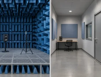
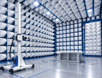
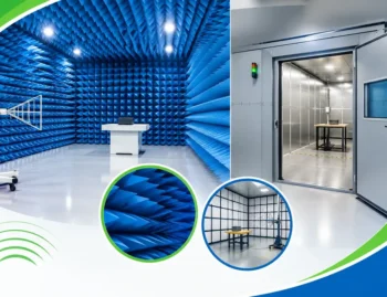
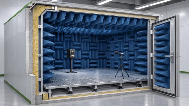
Fully anechoic chambers are lined on all six surfaces and suit antenna pattern measurement and wireless testing. Semi-anechoic chambers have a reflective floor and absorber on the other surfaces, and are the standard for radiated emissions testing. EMC chambers combine shielding with absorber for emissions and immunity work. Acoustic anechoic chambers are used for sound power and product noise measurement. Hemi-anechoic rooms serve larger acoustic sources standing on a hard floor. Compact antenna test ranges and vehicle-sized chambers cover specialised RF and automotive needs.
Standards and typical specifications
For EMC work, CISPR 16-1-4 governs chamber validation, including normalised site attenuation, with a typical tolerance of ±4 dB. CISPR 32 covers multimedia equipment emissions, and IEC 61000-4-3 covers radiated immunity, commonly from 80 MHz up to 6 GHz. Test distances are usually 3 m, 5 m or 10 m depending on the product size.
Military and aerospace programmes add MIL-STD-461G (tests such as RE102 and RS103) and RTCA DO-160G. Shielding effectiveness of 100 dB or better is common, and RF absorber normal-incidence reflectivity is often specified at around −40 dB or better at its design frequencies. Always confirm the exact limits against the current edition of each standard.
For acoustic chambers, ISO 3745 defines the qualification of anechoic and hemi-anechoic rooms for sound power measurement. The key figure is the cut-off frequency, below which absorption falls off. Good designs reach an absorption coefficient of at least 0.99 above that point, with cut-offs from roughly 50 to 100 Hz depending on wedge depth.
SOUND ATTENUATORS AND ABSORBER TECHNOLOGY
Two technologies decide whether an acoustic chamber performs. The first is the absorber itself: fibreglass or foam wedges whose depth sets the cut-off frequency, usually about a quarter of the wavelength at that frequency. The second is the set of sound attenuators fitted in the ventilation and cable paths. Without them, air-handling noise and flanking sound can ruin the background level, however good the wedges are.
Well-built acoustic chambers reach background noise levels below 20 dBA, and the best go lower. RF chambers use carbon-loaded foam pyramids for the higher bands and ferrite tiles for the 30 MHz to 1 GHz range.
Practical tip: specify the lowest frequency you will ever need to test, not just what you need today. Wedge depth, and therefore room size, cannot be changed later without major rework. Plan for equipment growth, turntable load and cable routing at the same time.
Planning your installation
Are you in the process of choosing or installing an acoustic chamber? Don’t hesitate to contact us. Our account managers and technical experts can help even if you are unsure what you need, and can work with you from the test standard and room size through to absorber selection and acceptance testing.